


O-ring calculation formula
Introduction
If you work with fluid systems, machinery, home appliances, or industrial equipment, you've definitely come across O-rings-small components that deliver big sealing performance. Although they look simple, getting the right O-ring size and groove design is crucial. A poorly calculated groove or improper compression ratio can cause leakage, premature wear, or even catastrophic equipment failure.
This guide breaks down the O-ring calculation formulas you need, using clear explanations and real engineering data. Whether you're an R&D engineer, procurement manager, or OEM designer, this page gives you a quick, reliable reference for designing a long-lasting O-ring seal.
Table of Contents
- What Is an O-Ring?
- Advantages of O-Ring Seals
- Types of O-Ring Compression: Axial vs. Radial
- Standard O-Ring Calculation Formulas
- Recommended Compression Ratios
- Groove Design Considerations
- Pressure, Extrusion, and Back-Up Rings
- Groove Depth & Width Reference Tables
- Frequently Asked Questions
- Contact Us (CTA)
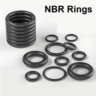
An O-ring is a circular elastomer seal with a round cross-section. It is widely used across industrial, mechanical, and electronic equipment for waterproofing, dustproofing, air sealing, and pressure sealing. Thanks to standardized dimensions and low cost, it remains one of the most reliable sealing solutions worldwide.
O-rings are popular because they offer several key benefits:
- Simple, stable structure
- Excellent sealing performance
- Minimal leakage under static sealing
- Low friction in dynamic applications
- Standardized sizes for easy replacement
- Low manufacturing cost & wide availability
- Adaptability to alternating pressure and vibration
Axial Compression (Face Seal)
Pressure is applied perpendicular to the sealing face.
Used when the O-ring is squeezed between two flat, parallel surfaces.
Examples: pumps, pipe flanges, filter housings.
Radial Compression (Side Seal)
Pressure acts parallel to the sealing face, compressing the O-ring from the side.
Examples: pistons, cylinders, hydraulic rods.

The following formulas apply to general design conditions:
| Parameter | Formula |
|---|---|
| Groove Width | O-ring cross-section × 1.3 |
| Groove Depth | O-ring cross-section ÷ 1.25 |
| O-Ring Inner Diameter | Groove bottom diameter ÷ 1.05 |
| Static Compression Ratio | 15% – 30% |
| Dynamic Compression Ratio | 8% – 15% |
Note: Actual values vary depending on material hardness, pressure, and operating environment.
The correct compression ratio ensures sealing performance without overstressing the elastomer.
| Application Type | Recommended Compression |
|---|---|
| Static Seal | 15% – 30% |
| Dynamic Seal | 8% – 15% |
| Low-Pressure Static | ~15% |
| High-Pressure Static | 20% – 25% |
| Vacuum Seal | 25% – 30% |

To maximize sealing reliability:
1. Groove & Clearance Fit
If the groove clearance is too large, the O-ring may be extruded at high pressure, causing permanent damage.
2. Material Hardness
70 Shore A → General purpose
90 Shore A → High pressure, extrusion-resistant
3. Pressure Requirements
Below 9.8 MPa (98 Bar) → Back-up ring usually not required
Above 9.8 MPa → O-ring must use back-up ring(s)
4. Single vs. Double Back-Up Rings
Single-direction pressure → One back-up ring
Bi-directional pressure → Two back-up rings
When pressure increases, softer elastomers may squeeze into the clearance gap and tear. To avoid extrusion:
| Pressure Level | Recommended Design |
|---|---|
| < 9.8 MPa | Standard groove, no back-up ring |
| ≥ 9.8 MPa | Add back-up ring(s) |
| > 20 MPa | Use 90 Shore A + PTFE back-up ring |
Example: Groove Dimensions for Standard O-Ring Cross-Sections
| O-Ring Cross-Section (mm) | Groove Width (×1.3) | Groove Depth (÷1.25) |
|---|---|---|
| 1.8 | 2.34 mm | 1.44 mm |
| 2.5 | 3.25 mm | 2.00 mm |
| 3.55 | 4.62 mm | 2.84 mm |
| 5.33 | 6.93 mm | 4.26 mm |
| 6.99 | 9.09 mm | 5.59 mm |
Example: Recommended Static Seal Compression
| Cross-Section | Compression (15–30%) | Final Squeeze (mm) |
|---|---|---|
| 3.55 mm | 0.53–1.06 mm | 14%–29% |
| 5.33 mm | 0.80–1.60 mm | 15%–30% |
1. Why is the compression ratio so important?
Because too little compression causes leakage, while too much causes wear, deformation, and early failure.
2. Can one formula apply to all O-rings?
No. Different materials, hardness levels, and working conditions require different groove designs.
3. Do high-pressure applications always require a back-up ring?
Generally yes, especially above 9.8 MPa.
4. What material is best for high temperature?
Viton (FKM) → up to 200–220°C
Silicone (VMQ) → stable up to 180–200°C
5. How do I choose between axial and radial seals?
It depends on equipment space, pressure direction, and assembly method.
If you're designing or sourcing standard or custom O-rings, Xiamen Jinshun Sealing Technology Co., Ltd. is ready to support your project with:
✔ 20+ years manufacturing experience
✔ ISO-certified production
✔ Custom materials, hardness, and dimensions
✔ Fast sampling & OEM/ODM service
✔ Competitive factory pricing for wholesalers and distributors
👉 Contact us today for technical support or a free quotation.
Our engineers can help you select the perfect O-ring size, groove design, and material for your application.